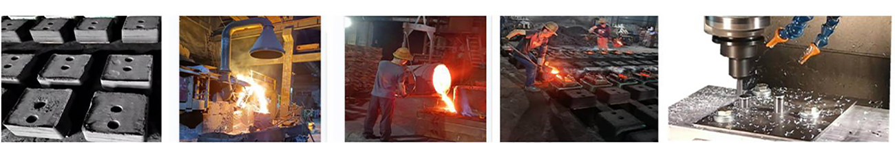
Large sand cast iron components are the backbone of many industrial systems. From pump housings and machine bases to municipal drainage products and heavy equipment frames, these parts are expected to withstand high loads, continuous vibration, pressure, and years of service. For manufacturers, producing defect-free Grey Iron Castings and ductile iron castings is essential because even a small crack can compromise structural integrity, increase machining costs, or lead to complete product rejection.
Among all casting defects, cracking is one of the most expensive. Industry studies estimate that casting defects account for 5–10% of total production losses, while cracks alone can represent 15–25% of rejected heavy castings, depending on product complexity and process control.
So, what actually causes cracks in large cast iron components, and how do experienced sand casting manufacturers prevent them?
Understanding Cracks in Sand Cast Iron Components
A crack is a fracture that forms when the internal stress inside a casting exceeds the strength of the metal. Unlike shrinkage cavities or gas porosity, cracks completely separate the metal and are difficult or impossible to repair for critical applications.
Cracks are generally classified into two types.
| Crack Type |
Formation Stage |
Primary Cause |
Typical Appearance |
| Hot Crack (Hot Tear) |
During solidification |
Restricted metal shrinkage |
Irregular, oxidized surface |
| Cold Crack |
After cooling |
Residual stress or external force |
Straight, clean fracture |
For large sand cast iron components, hot tears are far more common because thick sections cool slowly and undergo significant contraction during solidification.
Why Are Large Sand Castings More Prone to Cracking?
Compared with small castings, large iron castings experience much greater thermal stress because different sections cool at different rates.
The cooling process typically follows this sequence:
Molten Iron
      │
      ▼
Solidification Begins
      │
      ▼
Uneven Cooling
      │
      ▼
Thermal Contraction
      │
      ▼
Stress Concentration
      │
      ▼
Crack Formation
Several factors make custom sand casting of large components particularly challenging:
- Thick sections retain heat much longer than thin walls.
- Large dimensions create greater overall shrinkage.
- Complex geometries restrict natural contraction.
- Heavy cores increase internal restraint.
- Long solidification times amplify temperature differences.
For castings weighing several hundred kilograms—or even multiple tons—these effects become much more significant.
1. Uneven Wall Thickness Creates Thermal Stress
The leading cause of cracking is uneven wall thickness.
When one section solidifies while another remains molten, the cooler section becomes rigid first. As the hotter section continues to shrink, tensile stress builds until the material fractures.
Typical examples include:
- Centrifugal Pump Housings
- Valve bodies
- Hydraulic manifolds
- Machine tool beds
- Large gearbox housings
- Municipal drainage castings
These products often contain ribs, bosses, flanges, and reinforcing structures that cool at different speeds.
Cooling Rate Comparison
| Wall Thickness |
Relative Cooling Speed |
Crack Risk |
| 15 mm |
Fast |
Low |
| 30 mm |
Moderate |
Medium |
| 60 mm |
Slow |
High |
| 100 mm+ |
Very Slow |
Very High |
For this reason, experienced iron casting foundries try to maintain consistent wall thickness whenever product design allows.
2. Poor Gating and Riser Design
A well-designed gating system is critical for producing high-quality OEM iron castings.
If molten metal cannot adequately feed shrinking areas during solidification, isolated hot spots develop, increasing tensile stress and creating favorable conditions for hot tears.
An optimized gating system should:
- Deliver smooth metal flow
- Minimize turbulence
- Reduce oxidation
- Promote directional solidification
- Keep thick sections properly fed
Today, most professional foundries use casting simulation software before production begins.
Simulation can predict:
| Simulation Result |
Benefit |
| Hot spots |
Reduce hot tearing |
| Metal flow |
Prevent turbulence |
| Solidification sequence |
Optimize risers |
| Shrinkage prediction |
Improve yield |
Computer simulation can reduce trial production costs by 20–40% while significantly improving first-pass casting quality.
3. Sharp Corners Create Stress Concentration
Geometry plays a major role in crack formation.
Stress naturally concentrates at sharp internal corners instead of being distributed evenly throughout the casting.
High-Risk Design Features
- Sharp internal corners
- Deep pockets
- Square intersections
- Thick-to-thin transitions
- Narrow ribs attached to heavy walls
Example:
Poor Design

┌────┐
│    │
└────┘

Stress concentrated here ↑


Improved Design

╭────╮
│    │
╰────╯

Stress spreads evenly
Even adding a 10–20 mm fillet radius can dramatically reduce stress concentration in large castings.
4. Mold Rigidity Can Restrict Natural Shrinkage
The sand mold should support the casting while still allowing it to contract during cooling.
If the mold is too rigid, the casting cannot shrink freely, causing internal tensile stress.
Foundries carefully control:
| Process Parameter |
Effect |
| Sand strength |
Structural support |
| Binder content |
Mold rigidity |
| Mold hardness |
Dimensional accuracy |
| Core strength |
Internal stability |
| Mold collapsibility |
Shrinkage freedom |
Finding the right balance is especially important for large grey iron castings with complicated internal cavities.
5. Chemical Composition Affects Crack Resistance
The chemistry of molten iron directly influences shrinkage behavior and mechanical performance.
Typical Chemical Effects
| Element |
Influence |
| Carbon |
Controls shrinkage and fluidity |
| Silicon |
Promotes graphitization |
| Manganese |
Excess increases brittleness |
| Sulfur |
Reduces ductility |
| Phosphorus |
Excess lowers toughness |
For Ductile Iron Castings, proper magnesium treatment and inoculation are equally important because they determine whether graphite forms as spherical nodules instead of flakes.
Consistent chemical control helps reduce residual stress throughout the casting.
6. Residual Stress After Solidification
Even after the metal has completely solidified, internal stress continues developing as different sections cool.
Large castings often require several hours—or even days—to reach room temperature.
Residual stress may later cause cracks during:
- CNC machining
- Pressure testing
- Welding
- Transportation
- Assembly
- Field service
Many custom sand casting manufacturers perform stress-relief heat treatment for heavy castings weighing more than 500 kg, especially when tight machining tolerances are required.
7. Core Design Problems
Large castings frequently require multiple sand cores to create internal passages.
Poor core design can:
- Restrict contraction
- Shift during pouring
- Produce uneven wall thickness
- Create local hot spots
Accurate positioning using core prints and chaplets helps minimize internal restraint and improves dimensional consistency.
8. Incorrect Pouring Temperature
Pouring temperature has a direct impact on crack formation.
If the temperature is too high:
- Solidification takes longer.
- Grain structure becomes coarser.
- Thermal gradients increase.
- Hot tearing becomes more likely.
If the temperature is too low:
- Misruns occur.
- Cold shuts appear.
- Incomplete filling reduces casting quality.
Typical Pouring Temperatures
| Material |
Typical Pouring Temperature |
| Grey Iron |
1,350–1,420°C |
| Ductile Iron |
1,380–1,450°C |
Maintaining a stable pouring temperature is one of the most effective ways to reduce cracking.
9. Poor Inoculation Practice
Inoculation improves graphite formation and helps compensate for solidification shrinkage.
Proper inoculation provides several benefits:
- Better graphite distribution
- Lower carbide formation
- Improved machinability
- Reduced shrinkage stress
- Better mechanical properties
Without adequate inoculation, localized contraction becomes more severe, increasing the likelihood of cracks.
10. Cooling Too Quickly After Shakeout
Removing heavy castings from the mold before they have cooled sufficiently can create rapid temperature changes.
This thermal shock increases internal stress, particularly in large ductile iron castings.
Many foundries use controlled cooling schedules, allowing heavy castings to cool gradually inside the mold before shakeout.
Areas Most Vulnerable to Cracking
Some regions naturally experience higher stress during cooling.
| Casting Location |
Crack Risk |
| Thick-to-thin transitions |
★★★★★ |
| Internal corners |
★★★★★ |
| Rib intersections |
★★★★☆ |
| Flange roots |
★★★★☆ |
| Boss connections |
★★★★☆ |
| Heavy mounting pads |
★★★☆☆ |
| Uniform wall sections |
★☆☆☆☆ |
These locations deserve extra attention during product design and quality inspection.
How Professional Sand Casting Manufacturers Prevent Cracks
Reliable iron casting foundries combine engineering design with strict process control to minimize cracking.
| Prevention Method |
Purpose |
| Uniform wall thickness |
Reduce thermal gradients |
| Optimized gating and risers |
Improve feeding |
| Casting simulation |
Predict hot spots |
| Controlled pouring temperature |
Minimize shrinkage stress |
| Proper inoculation |
Improve graphite formation |
| Optimized mold properties |
Allow natural contraction |
| Stress-relief heat treatment |
Remove residual stress |
| Controlled cooling |
Reduce thermal shock |
| Non-destructive testing (NDT) |
Detect hidden cracks |
Many leading foundries also use finite element casting simulation and real-time temperature monitoring to improve casting quality before production begins.
Quality Inspection for Large Iron Castings
Even with optimized manufacturing processes, inspection remains essential for critical OEM iron castings.
| Inspection Method |
Purpose |
| Visual Inspection (VT) |
Detect surface cracks |
| Magnetic Particle Testing (MT) |
Identify surface and near-surface cracks |
| Ultrasonic Testing (UT) |
Detect internal defects in thick sections |
| Dye Penetrant Testing (PT) |
Reveal fine surface cracks after machining |
| Pressure Testing |
Verify leak-tightness for pressure-containing components |
For large pump bodies, valve housings, and hydraulic components, combining multiple NDT methods provides the highest level of quality assurance.
Selecting an experienced sand casting manufacturer is one of the most effective ways to reduce crack-related defects. A qualified supplier combines advanced simulation, precise chemical composition control, optimized gating design, controlled pouring temperatures, and comprehensive inspection to produce reliable large sand cast iron components, grey iron castings, and ductile iron castings that meet demanding industrial performance requirements. By controlling every stage of the casting process—from mold design to final testing—manufacturers can significantly improve product quality, reduce rejection rates, and extend the service life of critical iron cast components.


 IPv6 network supported